
GCSE Maths and English Revision Tool https://gcse-prep.toolsforteaching.co.uk/
https://gcse-prep.toolsforteaching.co.uk An AI-powered GCSE revision app for Maths, English Language and English Literature, supporting AQA, Edexcel (Pearson) and OCR exam boards. Features Study Games Video Lessons Curated links to the best free GCSE …
Flowchart Boss
This is Flowchart Boss – a flow charting app with built-in self-paced teaching using only those symbols that appear in the Pearson T-Level. No login, no cost, no limitations: just …
🎵 The Six Vs of Big Data 🎵
(Upbeat pop/rap style) [Verse 1]Every click, every swipe, every post online,Data getting bigger all the time.Companies collecting day and night,Trying to turn information into insight. Servers humming, networks glow,Millions of …
Python Playground
Python Playground: https://python.toolsforteaching.co.uk A browser-based Python IDE that runs entirely client-side — no server, no installation, no Python runtime required on the host machine. Built for use in Further Education …
CSS Fundamentals
CSS Fundamentals Overview CSS Fundamentals is a purpose-built interactive teaching tool for T Level Digital Production, Design and Development students. It replaces static slides with live, hands-on exploration: students drag sliders, …
ReactCopier
If, like me, you seem to be constantly transferring source code in node/react from one machine to another, especially before you are ready to push what you are working on …
CPU Fetch–Decode–Execute Simulator
https://cpu.toolsforteaching.co.uk/ The CPU FDE Simulator is an interactive, browser-based teaching tool that visualises every micro-operation inside the CPU’s Fetch–Decode–Execute cycle. Students watch a glowing spark travel between registers and memory along colour-coded buses, …
CM-HTML: a browser-based tool for teaching web design
Most schools and colleges have highly controlled IT access and this naturally means that useful tools for teaching development are limited. One of my particular areas of interest is in …
Hardware Labeller — Hardware Components Teaching Tool
https://label.toolsforteaching.co.uk/ The Hardware Labeller app is a fully browser-based, interactive teaching and self-study activity designed for students aged 16–19 studying T-Level Digital (Software Development). It covers every component and device specified in Learning Outcome …
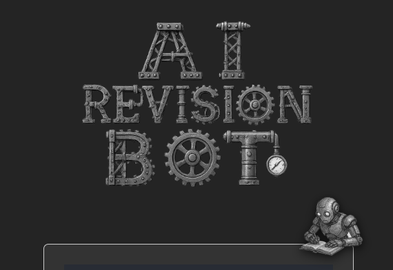
AI Revision Bot goes live across college!
We have started to use the AI Revision Bot across the Department of ITDD at Exeter College to support learner’s revision. Overall the feedback is very positive – apart from …

SQLSim – Teaching aid for learning SQL
This is a student-safe environment to learn and tinker with SQL queries without the complexities of setup or the risk of compromising shared data. All processing happens in a virtual …

CodeMonkey PPT Extensions – On Screen Timer
I usually develop Office extensions in response to a given need. My mentor suggested that an on-screen timer would help keep the time limit in my student’s mind when they …

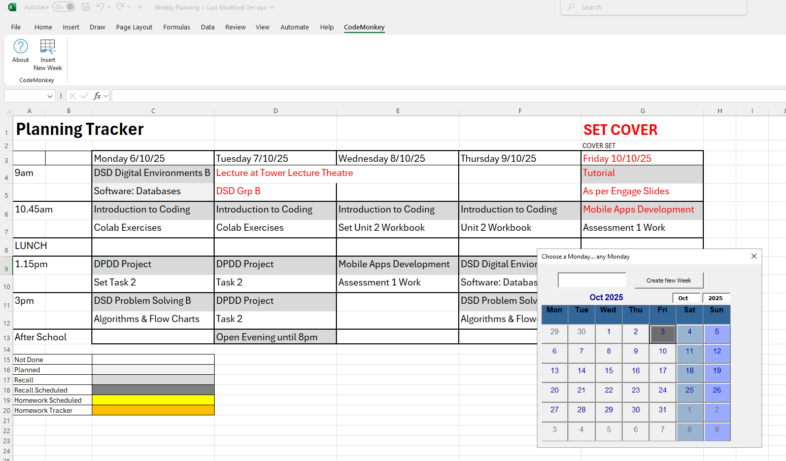
Weekly Planning Spreadsheet
One of the things that is really overwhelming for an ECT is the amount of Planning you need to get together. More experienced teachers tell me it gets much better …


Work better not harder: ChatGPT and Recall Quizes
We all know the benefits of recall of previous learning, especially when spaced as we move information from working into long term memory For this reason, I start all my …
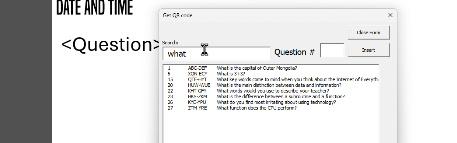
Further Kallbak Improvements: searchable insertion of questions inside PowerPoint
Further Kallbak Improvements: searchable insertion of questions inside PowerPoint I decided to make the UI of the PowerPoint element of Kallbak better, so enabled the facility to see all the …
Kallbak now features Likert Scale Questions
Kallbak now features Likert Scale Questions Likert Scales are the 1-5 rating scales used all over the place. They have a long history in research questionnaires and have been seriously …
Kallback Powerpoint Module: Improved Wordcloud
Kallback Powerpoint Module: Improved Wordcloud Whereas creating a wordcloud within a web-based App was relatively easy, creating that inside PowerPoint (one of the key features of Kallbak) was quite challenging, …

Form multiple drives into a single mountable drive on Ubuntu
Form multiple drives into a single mountable drive on Ubuntu This is a script which does the above. I have three additional drives on my Ubuntu box which I wanted …

Teaching the Bubble Sort Algorithm using Pringles
Teaching the Bubble Sort Algorithm using Pringles Creative Commons Simon Rundell CC NC-BY-SA 2025. Use freely. Or make your own. I just did it on my phone.
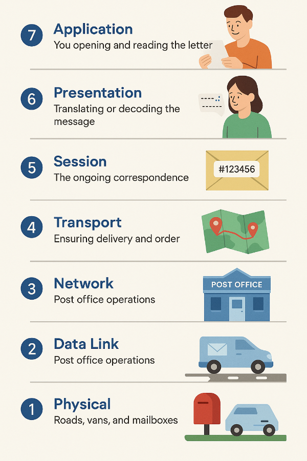
Lesson Notes: Network Protocol Layers
A network layer model helps break down communication into smaller, more manageable functions. The most common model is the OSI (Open Systems Interconnection) Model, which has seven layers, each responsible …

Lesson Plan: Teaching Cybersecurity without touching technology
This is the lesson plan which got me the job. I couldn’t be sure of the resources I would have available, so I opted to teach about the CIA Model …
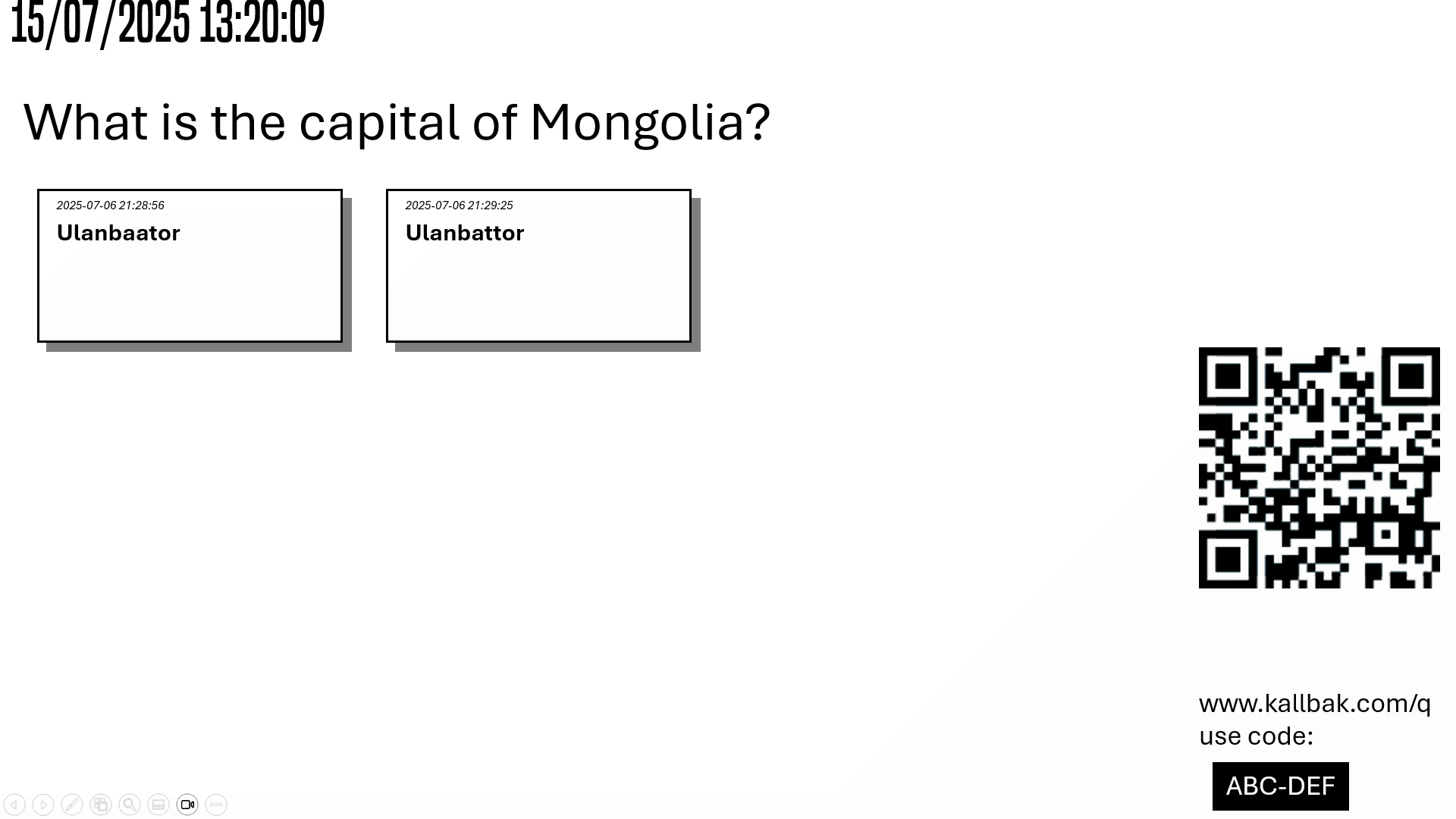
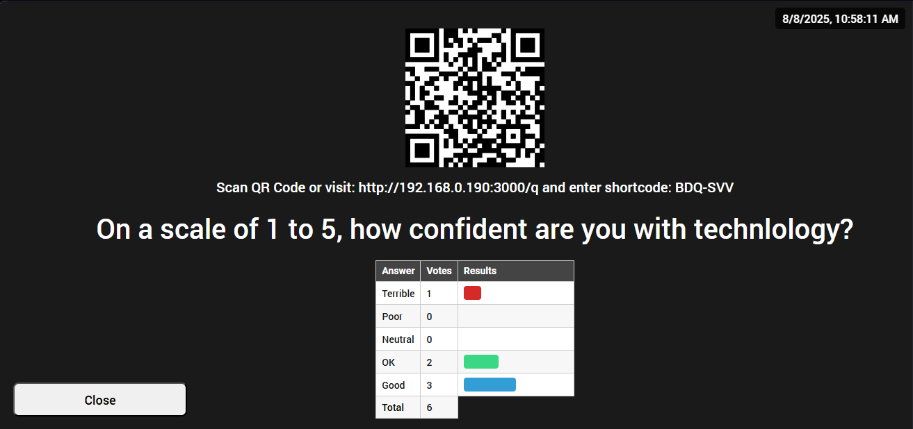
Kallbak – student engagement in real time.
Many schools often ban Mobile Phones as a distraction, but in Computing we view them as tools – both a platform for development and a means of using technology to …
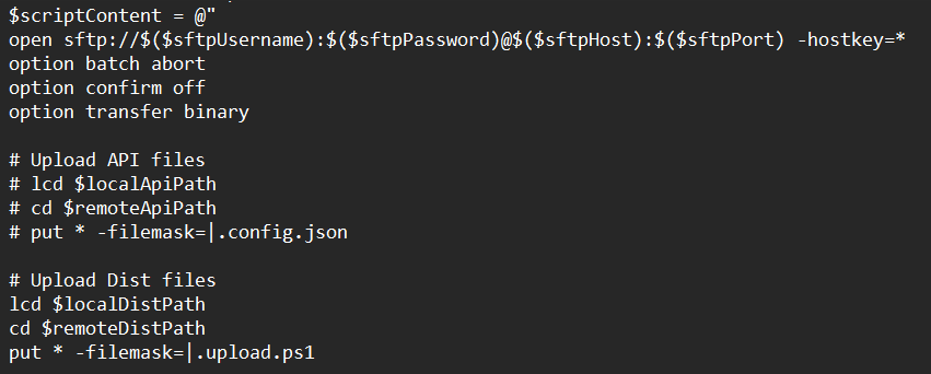
Upload PowerShell FTP Script using WinSCP command line
There are times when you need to upload a selected batch of files somewhere. In my case, as I am shipping React code to live after it has been built. …
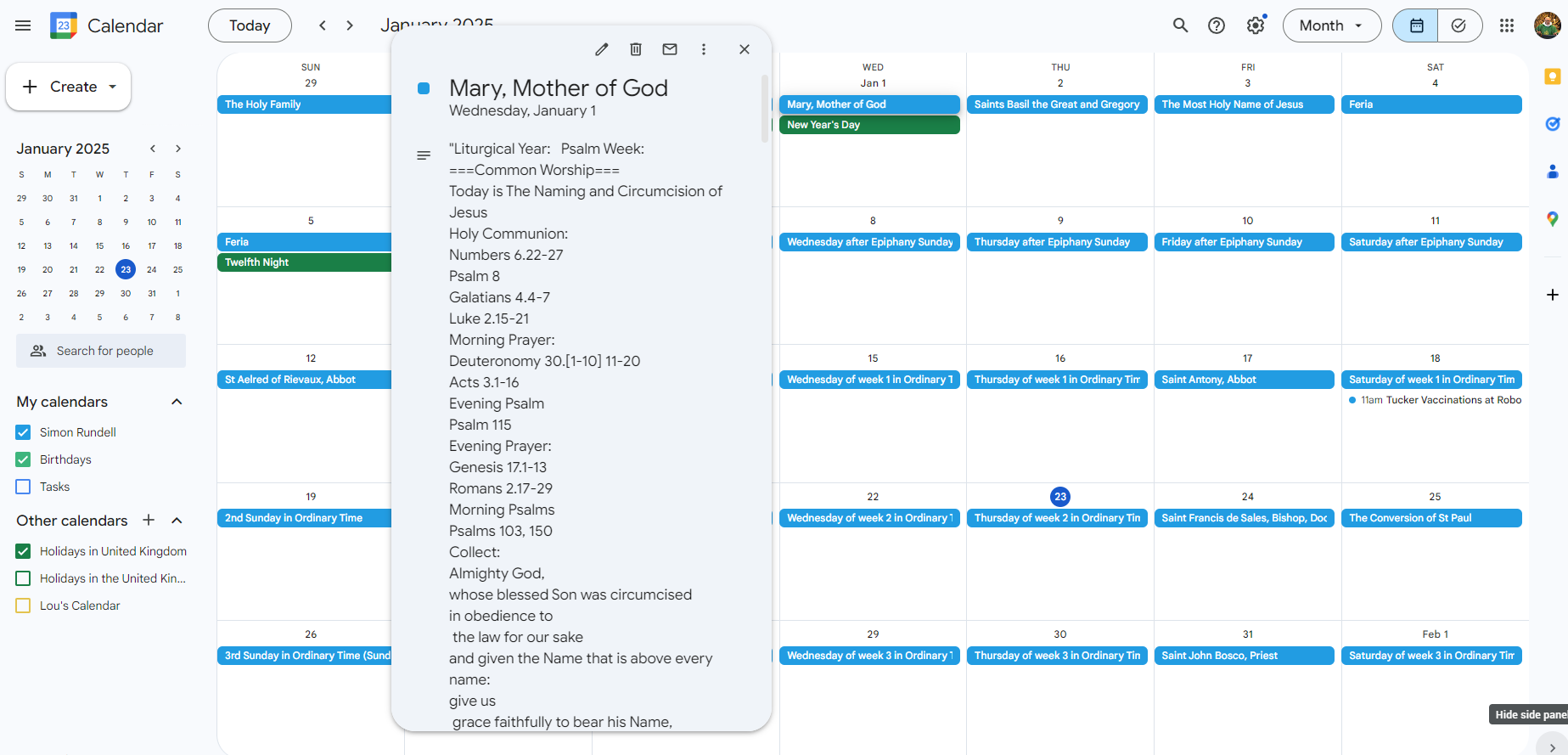
Fr Simon’s Electric Ordo Advent 2024-Advent 2025
Each year I produce a liturgical calendar of Bible readings based upon Common Worship and the Roman Lectionary which is compatible with Google Calendar, Microsoft Outlook and Mac iCal. This …
A Text Adventure Game in Python
I have been undertaking a course on Python for some extra credit as part of my PGCE through ExCode. Part of this has been to create a text-based adventure game. …
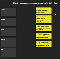
Question match site
This little revision aid comes out of a less ambitious idea: I wanted to illustrate the matching of statements to headings using a little drag and drop. It was originally …
Blur CSS Filter – a game changer for my UI
This is such a cool effect, bringing an object (usually a div) up on screen
The Little JupyterHub (TLJH) Configuration Guide
I tried to install regular JupyterHub about a dozen times. Each time I found myself in a morass of configuration and authentication problems, and when it came to the crunch, …

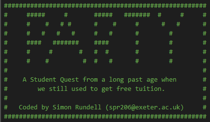
Pirate Pete’s Python Programming Treasure Quest
I’ve been working on JupyterHub Notebooks recently – a collaborative document format which can run Python code in small code windows. It’s excellent for teaching and developing skills in programming. …